
The end of the axle tubes sport a 6 bolt circular flange to which a set of spacers (more later) and the brake mounting plate affix. Outboard of this plate is the half-axles along with its bearing/hub combination. The hub mounts to the half axle on a conical surface that gets incredibly tight by the stresses of driving. Hub removal is therefore quite the chore, and all sorts of ingenious ways have been devised to do this. I resorted to taking it to Dave’s Place in Hendersonville NC. Basically it’s his farm house and outbuildings, which are filled with old Triumphs. He runs a repair/restoration shop out of one of them. Anyways a BFH later, and they were separated. I cleaned out the bearings and found some metal shavings, but they spin smoothly so I don’t plan to replace them. I’ve read that one should test them under load, but I had no way of doing that. Hubs had their oil seal removed, they were cleaned and painted for reassembly.
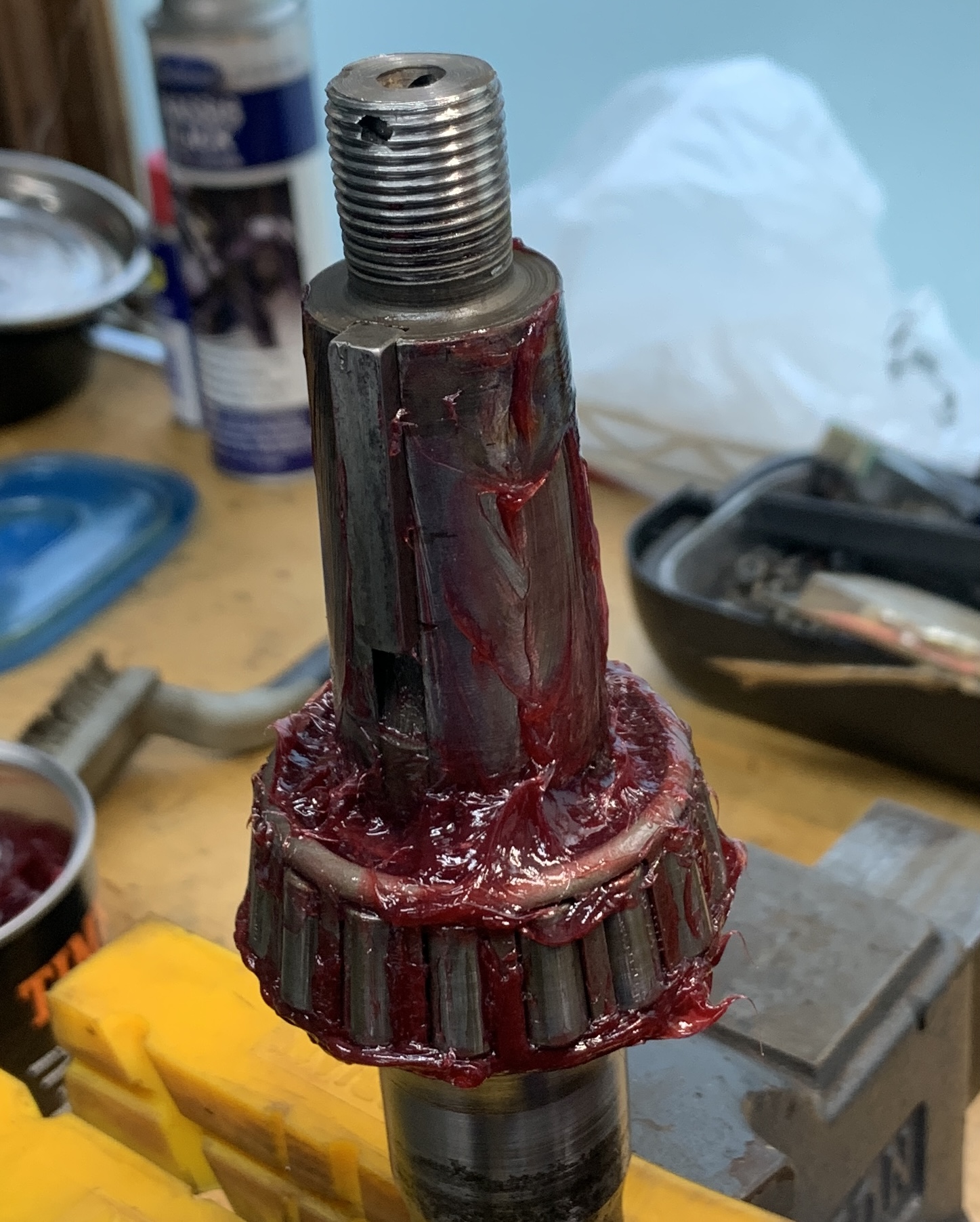
One issue I faced is the mounting bolt at the end of the half axle. It was mushroomed during hub removal. Phillip in the machine shop was kind enough to help me with this problem. Chucked it in a big lathe and was able to work it down with a thread file enough to get a 3/4-16 die on the end of it. Looks awesome! I could have never done this at home.

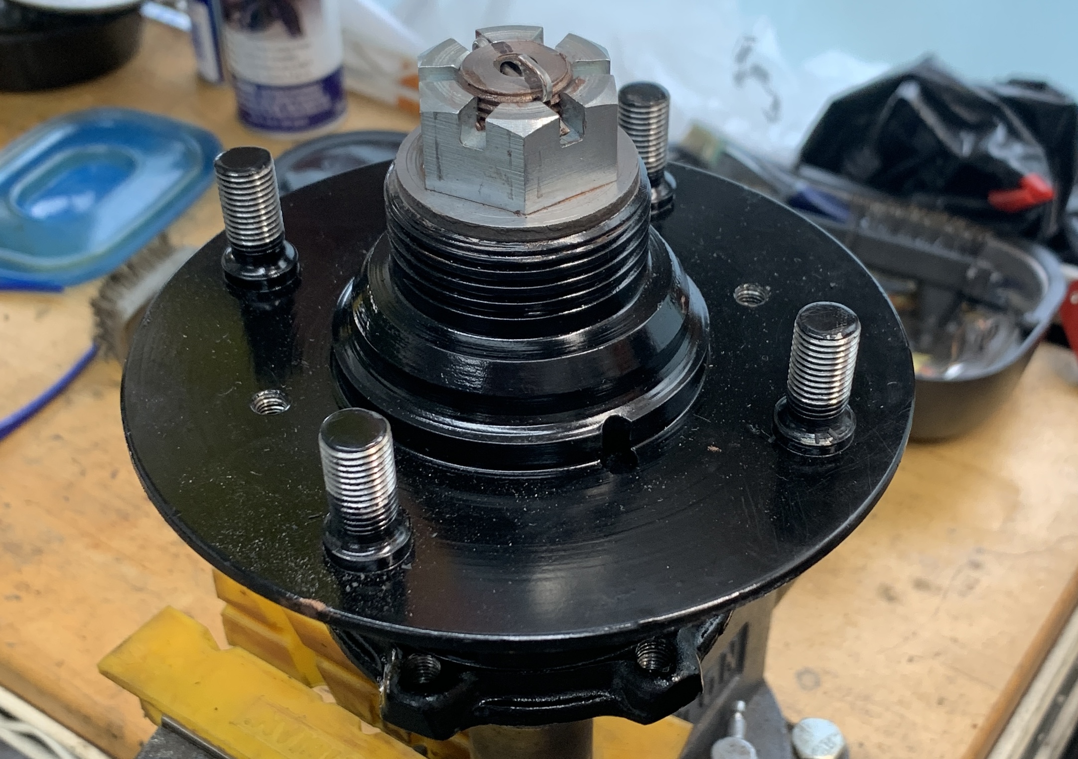
After that it was time to mount the keyway, pack the bearing and assemble.
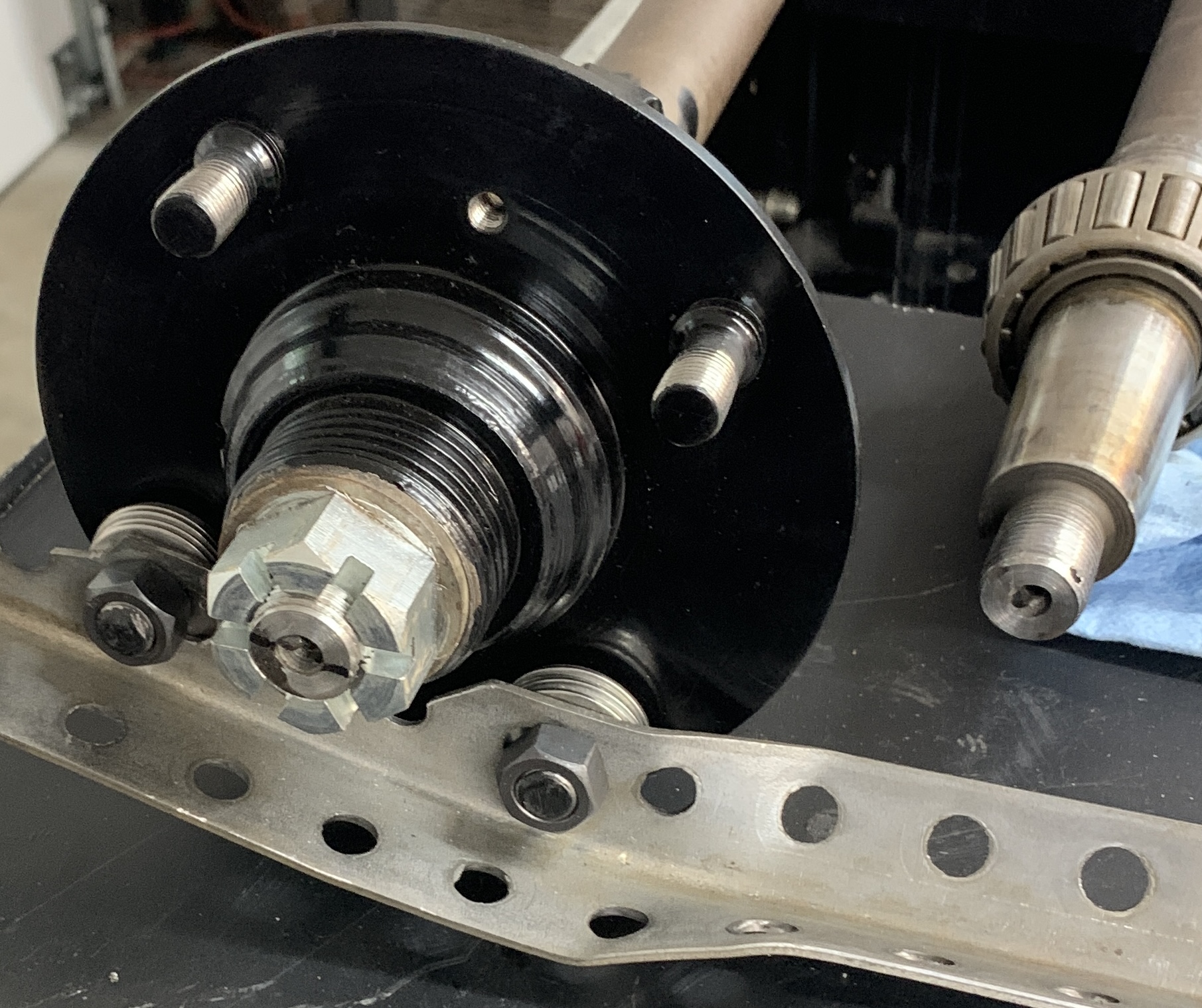
Nut goes on at 125-140 ft lbs… enough force to bend the support.
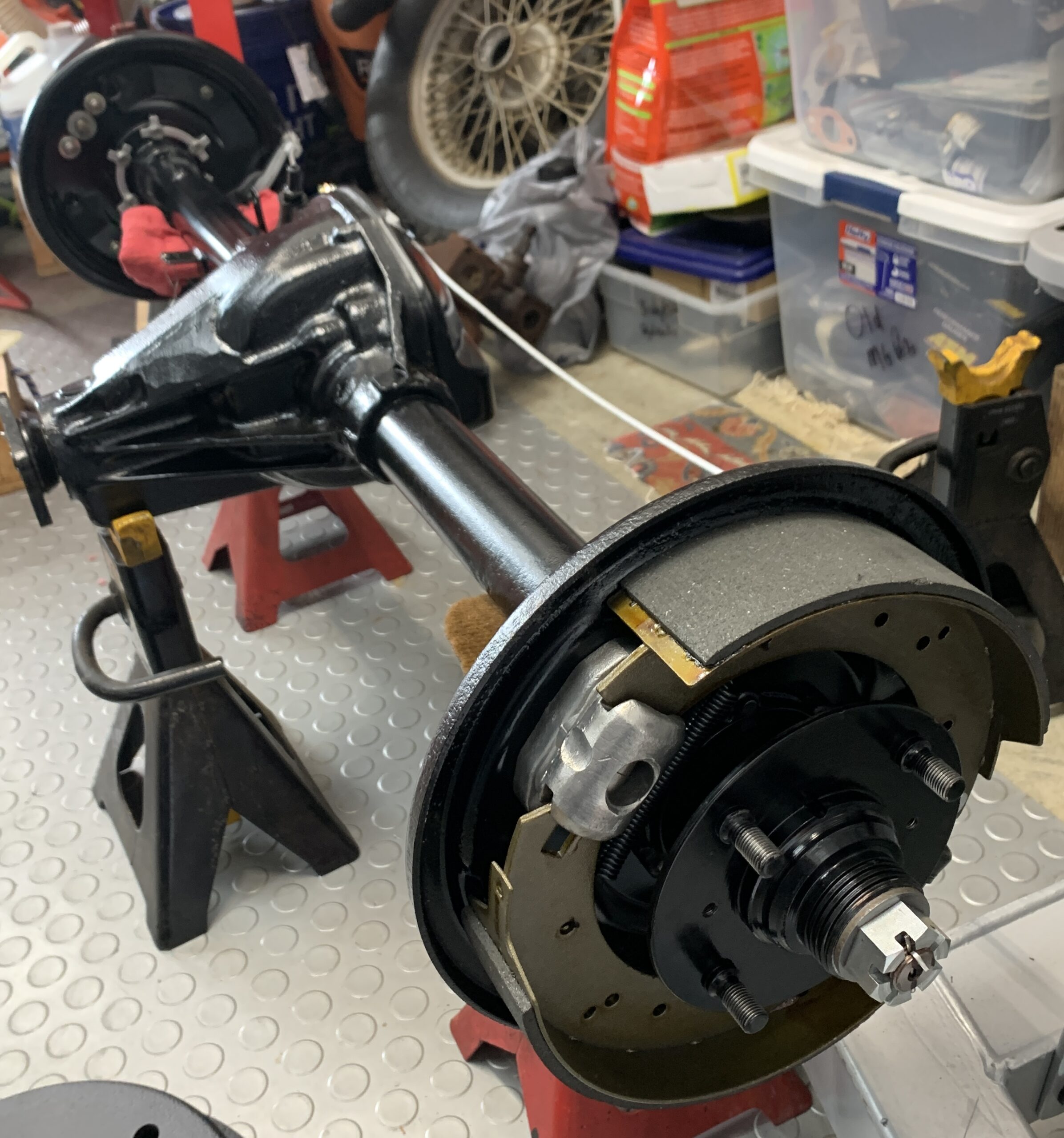
With the hubs installed, it was time to add the outer tube oil seal, then brake plates. I reused the previous shim packs between outboard axle tube flange and brake plate for the reassembly, and then snugged everything down.
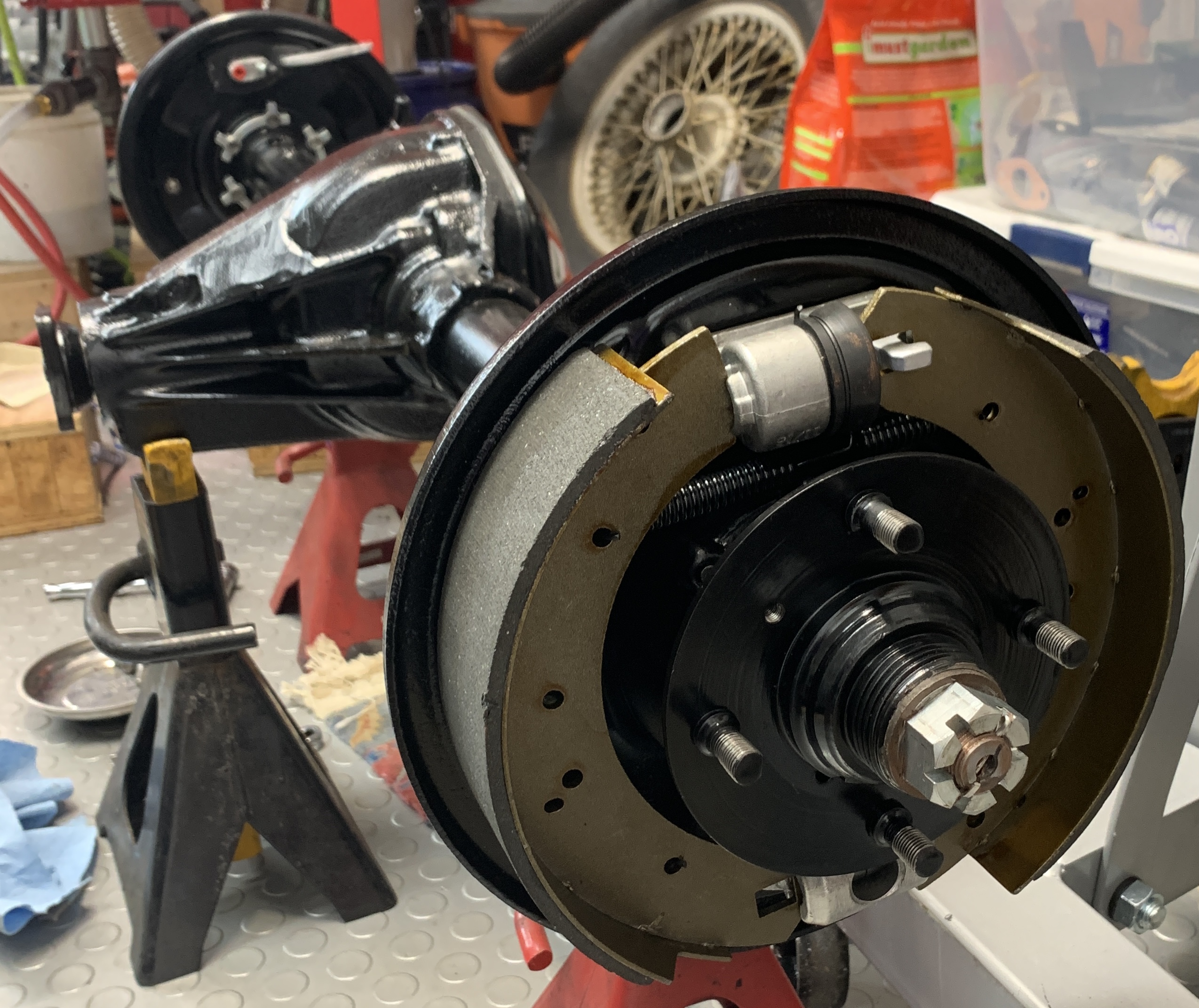
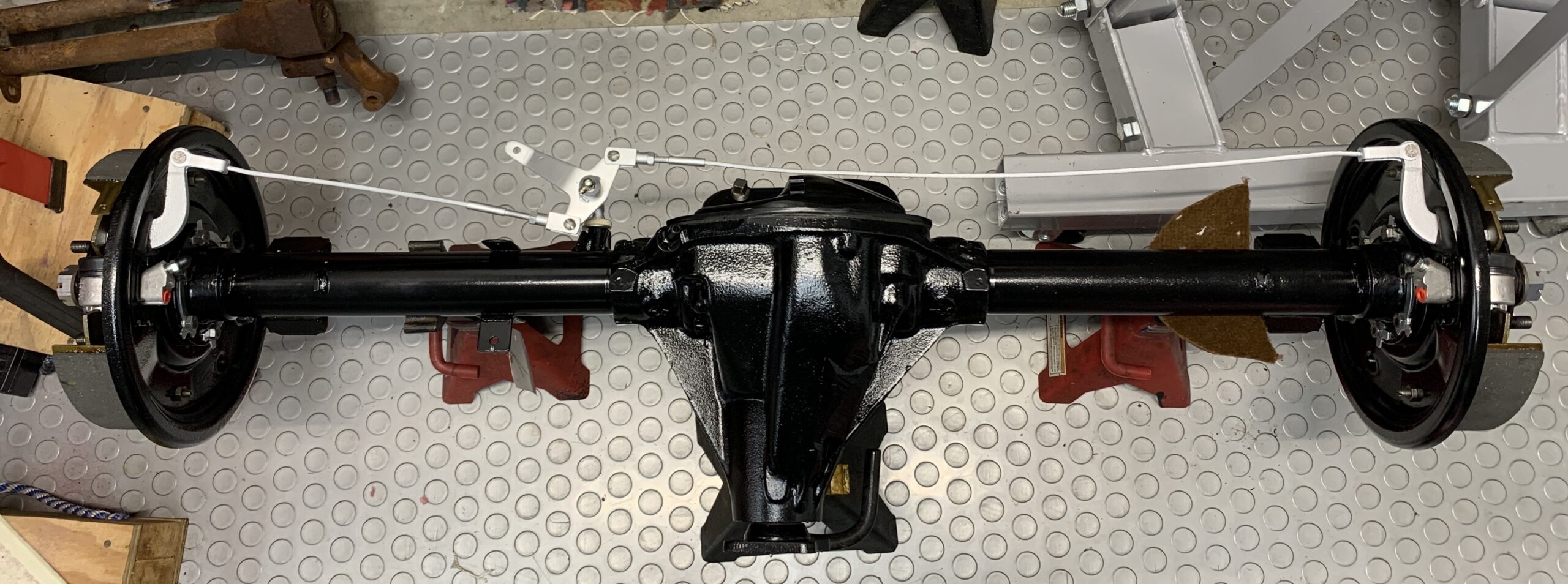
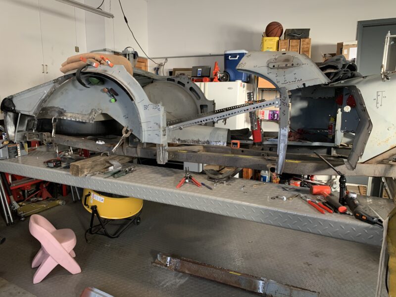
In this photo, the brake plates are reversed. Per the shop manual, the lever arm for the hand brake points in the direction of the forward wheel rotation. You can see in the background that it is pointing towards reverse. So disassemble, swap them out, and retighten. You can also see in the rear brake plate the fold over lock washers that ensures that Hub won’t come loose. That would be bad… Here they are reversed and properly oriented. I oriented the brake plate so the level arm pointed rearwards and down so the run to the e-brake was clean and didn’t rub on anything. This also sets the position of the brake cylinder position. Since I didn’t have a reference photo, I’m going with this arrangement unless I see otherwise.
You’ll notice that I have also installed the hand brake cabling to the pivot arms. This is a gratuitous shot from before I switched the left/right brake plates.
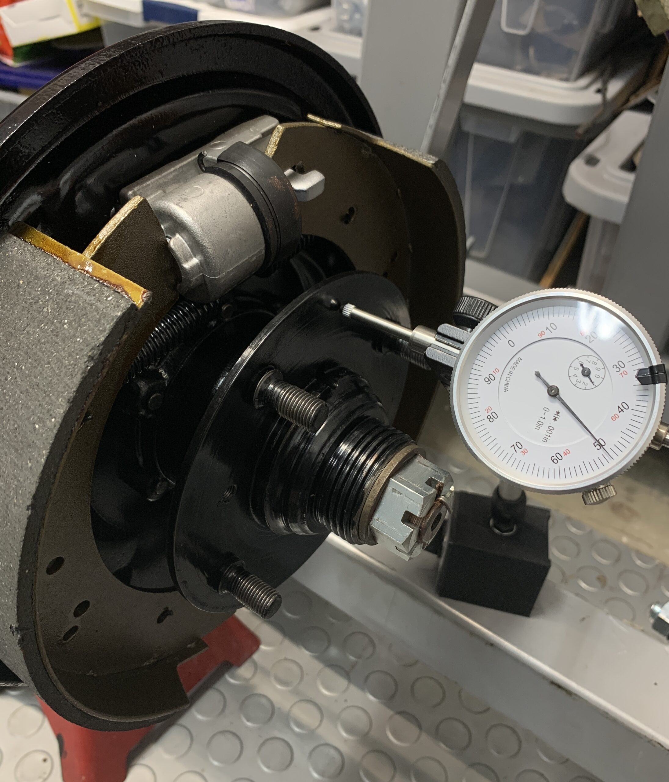
Once everything is snugged, it is important to measure the end float of the hub and axle. The factory spec is 0.004-0.006″ and I measured 0.005″ for both sides, so happy with that. This is not completely settled yet though as the manual prefers to have the overall stack thickness be as close to the same on both sides.
Shim Stack: Drivers Side (3) 0.0340 + 0.0060 + 0.0160 = 0.0560″
Shim Stack: Passenger Side (2) 0.0160 + 0.0145 = 0.0305″
I could remove the 0.0160 from the DS to make it: 0.0560 – 0.0160 = 0.0400, PS: 0.0305 + 0.0160 = 0.0465. These would be a lot closer to equal on both sides, but I’m not certain if messing with the stacks themselves will actually affect the end float. Before I’m satisfied, I’ll need to test it out.
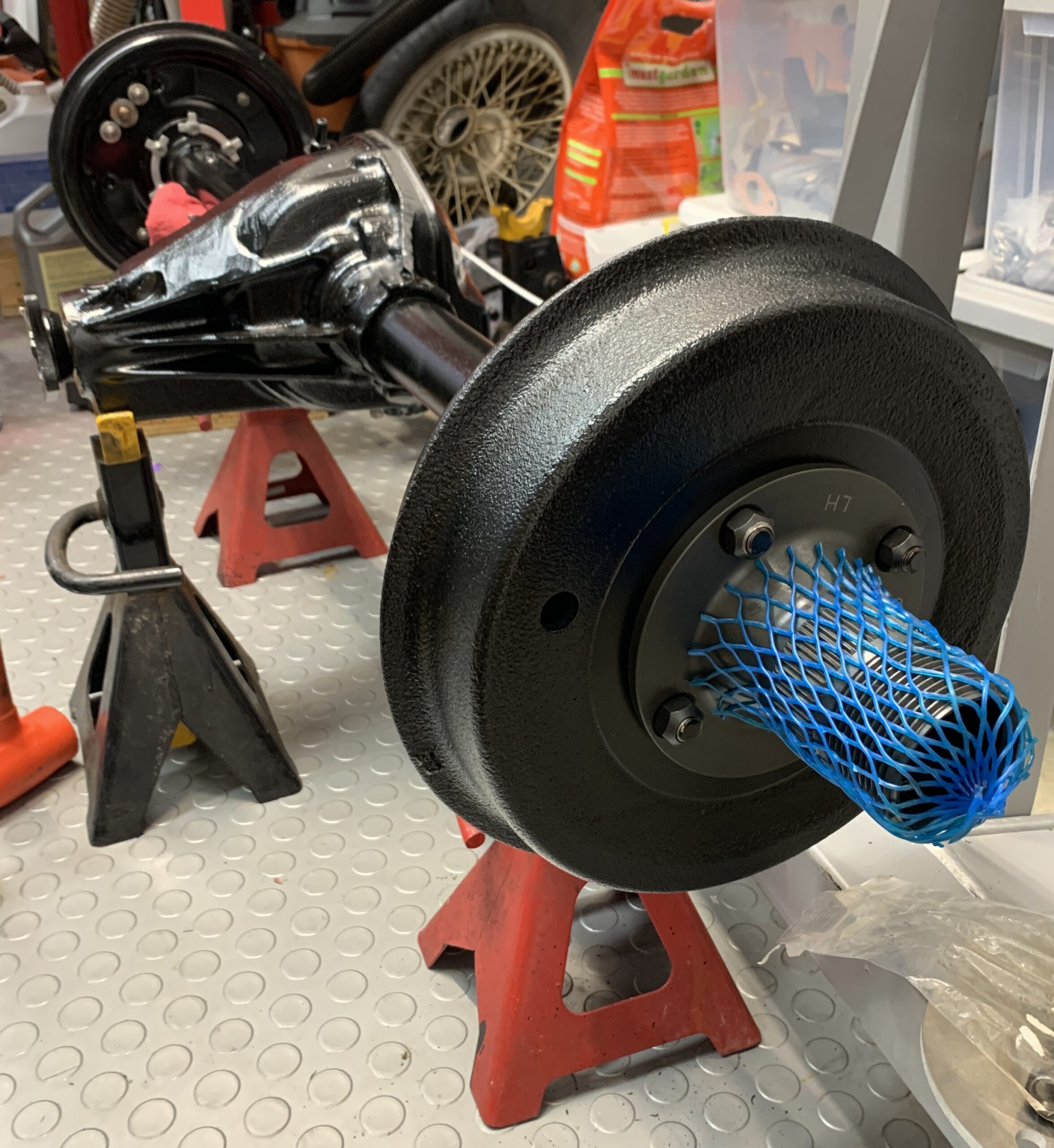
Once I’ve double checked the end float I’ll put on the freshly turned brake drums and rear axle TS50950 will be ready to put away until the frame is repaired and painted.
update: changing the shims tacks as shown led to nearly identical end floats (0.0050) so thats what I’m going with.
Add the freshly turned brake drums and new wire wheel hub adaptors, and voila, job done. Too heavy to move on my own again… must wait for giant to come home from college.
Recent Comments