Radio: It’s more than AM/FM songs to listen to while you drive! It’s light! As a reminder, radio is a long-wavelength section of the electromagnetic spectrum. Although these observations were not taken in optical wavelengths, I was still able to make use of the radio data (with Skynet’s radio cartographer algorithm) to create a few radio images with (arbitrary) colors!


For this experiment, I brought my view back to the moon, this time with access to a radio telescope in Green Bank Observatory (GBO) in West Virginia (Although small for a radio telescope, it’s still 20m in diameter, 150 tons, and 6 stories tall). We all know that the amount of visible light (wavelengths that we can see) on the lunar surface changes (seen through the phases) every day. However, with this access, I was able to ask the question of whether or not the same happens at radio wavelengths!
For the radio observations (using Skynet, just like last time), my groupmates and I placed one for the moon and one for the calibration source, which was Virgo A (Messier 87 | 3C 274). These observations were repeated 4 days later, when the moon phase had shrunk significantly (61% to 21%) in the visible.
To properly measure the brightness (flux density) of the moon, I had to additionally measure the brightness of another object of known brightness in the night sky around the same time. This would be the “calibration” source, so the arbitrary units of flux density that change slowly over time could be converted to standard units. My group used Virgo A to be the calibration source.
To observe Virgo A and the moon (my group responsibility was Vir-A), I used GBO’s 20m L-band receiver (detects wavelengths 1300MHz – 1800MHz) alongside low spectral resolution mode with the HI bandpass filter (narrows the detector’s response to 1355 – 1435MHz) all to get around a lot of man-made interference (those radio stations… and more). For the “path” that the radio telescope dish follows (to make an image with a fixed FOV sensor), I used the “Map” path type. This map size was specified by beam widths of Right Ascension & Declination 6 (RA ~4.8 degrees, Dec ~4.5 degrees). I chose the raster/sweep direction to follow RA with 1/5 Beam Width gap between & along sweeps. Finally, I chose to integrate/expose for 0.3 seconds at each grid point (how fast the telescope moves). My groupmates repeated the same observation for the moon (delayed and non-delayed).


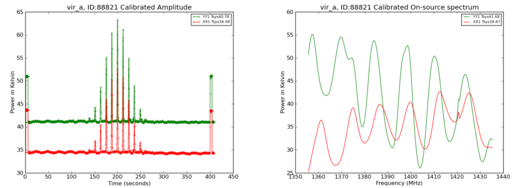
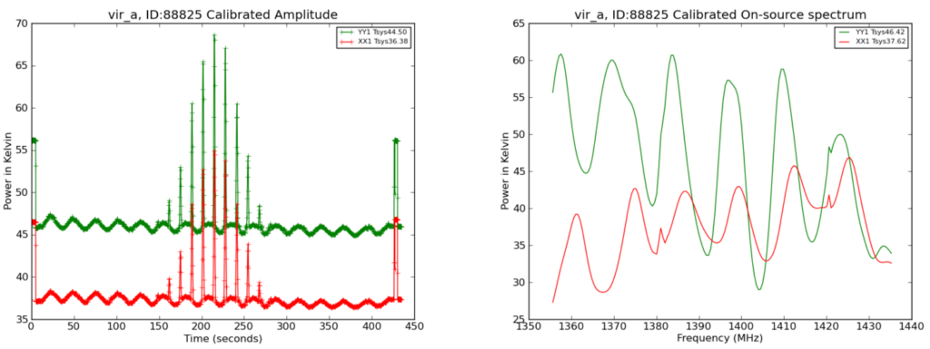
For both of the plots on the left, the brightness detected in each of the telescope’s two, oppositely polarized channels vs. time are distributed (brightness / all observed frequencies).
For both of the plots on the right, the brightness detected in each of the telescope’s two, oppositely polarized channels vs. frequency are distributed (brightness / all observed times).
The preliminary images provided by GBO are full of defects, so that’s why I created my own (at the top of this post). I did so using one of Skynet’s algorithms (Radio Cartographer). After choosing some image processing options, making sure to skip over radio frequency interference (RFI) and cleaning up any other contaminations, the image was created! The colors in these images are completely arbitrary & artificial, they’re just used to visualize the brightness of the source and its surroundings.
The next step was to measure the brightness of the sources (4 images)! I used Afterglow’s photometry to measure the flux density of the center of each source in noise-source units (before calibration). To convert these flux densities into physical units, we used the Jansky (Jy). 1 Jy = 10^(-26) W/m^(2)/Hz
After doing the calculations to calibrate the flux densities, I was able to calculate the temperature using this formula:

Where:
T = Temperature (in Kelvin)
S = flux density of the moon
k = 1.38 * 10^(-23) J/K — Boltzmann’s constant
c = 3.00 * 10^(8) m/s — speed of light
v = 1395 MHz = 1.395 * 10^(9) Hz — central frequency
R = 1737 km — radius of the moon
This is what the table looked like:

As we can see in the table, the Moon Flux Density increased (in the radio) as the moon phase decreased (visible). (Wow! That’s strange!)
This shows us that what we’re actually looking at is emitted light, not reflected! This happens because the moon is still heated by the sun, even when we can see less (or no) moon phase! The sunlight is absorbed and then re-emitted as radio, which we picked up in this experiment.
All things emit electromagnetic radiation based on temperature!
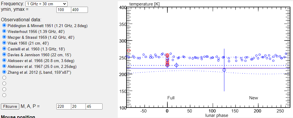
And upon further investigation, we can calculate the temperature of the moon (as seen in the table & the formula above)! We found the temperatures of the moon during the two different phases, 61% & 21% full, were 234 K and 225 K, respectively. This is very similar to the various professional measurements found on this site, which are all between ~200 K to ~270 K, many of which are around 230-250. My values fall perfectly in that range, so I guess you could say I’m a professional 😎 (only jokes).
Here’s a snapshot of those professional values I was talking about:

Lunar Radio Temperatures
These temperatures show that the moon is, in fact, re-emitting sunlight as it is warmed, even when the phase we see is not as full (the moon is always being heated, regardless of what phase we see).