Radio telescopes are definitely something unlike any other. Yes, radio and optical telescopes do share the same end goal in their act: sending off waves to an object—such as the Moon in this case—to receive some type of image. Yet, radio telescopes seem to do things that opticals cannot, such as that you receive radio observations during the day and not have to worry about the sunlight interfering with your observation. Now that I have given some way to building the superbness of radio telescopes, let’s dive into the details that concern both my radio observation and my group members’ observations as we compared each of our results.
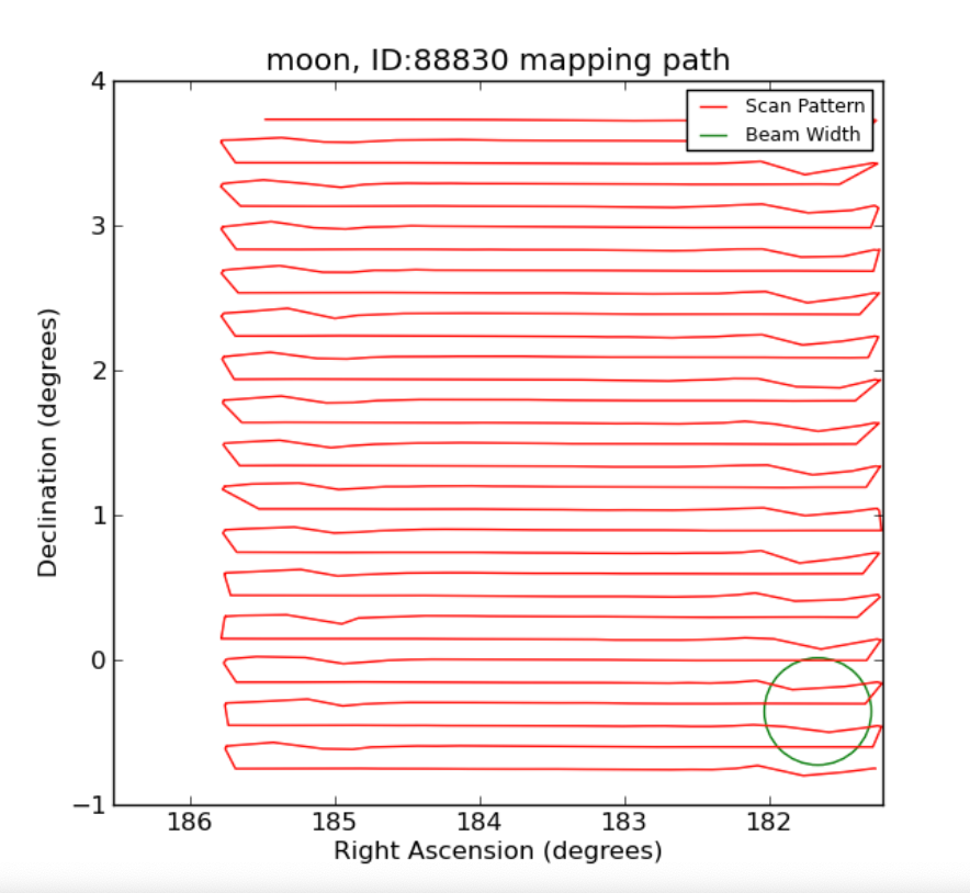
My radio observation came from Skynet’s radio telescope that is located at the Green Bank Observatory in West Virginia and is 20 diameters in size. This single-dish radio telescope was able to receive my observation of the Moon that was sent out on January 13, 2023. Out of the many mapping patterns that radio telescopes are known to use, the pattern used at the Green Bank Observatory was the “raster” pattern—it takes on a rectangular grid that approximates wavelengths in a horizontal manner. In other words, the telescope moved back and forth in a pattern. It also is important to note that on the mapping paths, such as the one shown below, there can be interferences with the satellites. These interferences will be detected by the L-band and show up on the map as uneven lines as the satellite could’ve been pushed off course the wind momentarily. The telescope had a duration sweep of 9 seconds with 23 sweeps and 6 beam widths. I set the observation to acquire the telescope to have gaps with a 1/5 beam width, there was a 4.5 minute observing time. Also, the radio observation utilized a ‘HI’ filter that detected the frequency of the observation at 1396 MHz (which attempts to capture data with limited interference).

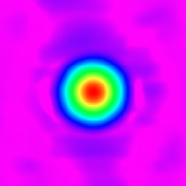
Now, let’s dive into the real masterpiece that I wanted to share with you. With the help of Skynet, I was able to capture a radio image of the Moon that details its varying levels of brightness. The image captured is definitely something different than that of an optical observation. In the observation displayed below (Figure 2), you can see an array of different colors—all in which have different meanings. The use of purple means that the energy received from the Moon are dull and the use of the color red means radio waves are bright. Again, these colors portrayed below in the observation are artificial and were used to display the information received with the radio waves captured from the Moon. The image also displays “airy rings” around the primary figure—shown in Figure 2. This seemingly discolor is what actually aids the process of measuring the brightness of this radio observation. I also want to note that to enhance the “airy rings,” I used a ‘Faint Target’ preset along with putting a ‘Square Root’ stretch mode on the image.

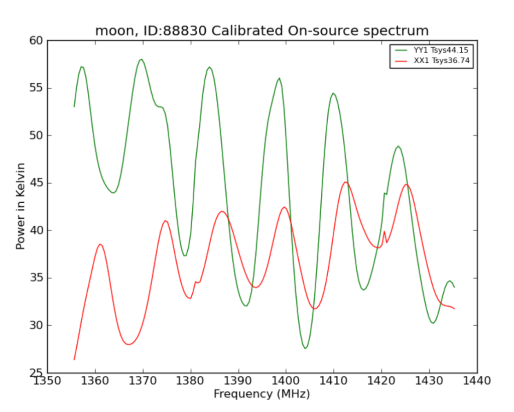
After getting the observation back, the next plan of action was to measure the Moon’s brightness—otherwise known as flex density. As we sent in observations that received the image displayed in Figure 2, we also received another observation known as the calibration source. This observation—displayed as Figure 3—depicts the observations different levels of brightness through displaying the various levels of frequencies captured from the radio waves reaching us from the Moon. In other words, Figure 3 shows the brightness from the entire observation time. Something that I found interesting to note about Figure 3 is that the slight jerks in the lines is due to human-made transmissions interfering with the observation despite it being in a National Radio Quiet Zone.

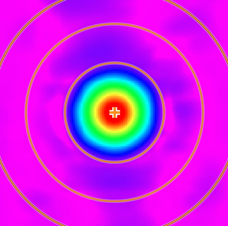
Another key step in figuring out the flex density of the Moon was through using aperture photometry. This means to draw a aperture (a big circle) around around the main point to add up all of the pixels within the circle, and then to finish off by drawing two more circles around the source to measure the background levels within them—which is depicted in Figure 4 below. In summary, the flux density came to be 3,889.581 in “noise-source” units.

As I mentioned previously in this blog, I wanted to also share mine and my group member’s findings. So, after we all collaborated on our results of our observations of the moon, which amounted to a total of 4 observations—all targeted at the moon but 2 of the observations were delayed (meaning that they caught the Moon’s radio brightness at a different phase)—we were able to concluded our findings. This is the results that we found: the two radio observations targeted at the Moon and ‘Vir A’ on January 13, 2023 depicted the Moon Phase of 61%, a Moon flux density of 3.763478138 (‘Vir A’ units), a ‘Vir A’ flux density of 229.2 (jy), at a distance of 391872.496 (km), and a temperature of 234.168826 (k). The second set of results found entailed two radio observations of the Moon and ‘Vir A’ but were delayed as they were taken a few days later on January 17: the Moon Phase of 21%, a Moon flux density of 4.152925908 (‘Vir A’ units), a ‘Vir A’ flux density of 229.2 (jy), at a distance of 366442.938 (km), and a temperature of 225.9524272 (k).
When comparing the flex density of the Moon’s phases, and noticing that there is not a significant change in the values provided, it is concluded that we are observing the Moon’s “thermal energy”—a type of energy is emitted from beneath the lunar surface. Also, when comparing the measurements that me and my group calculated to the professionals (which was done on the site: https://portia.astrophysik.unikiel.de/~koeppen/JS/LunarTemps.html) I found that the professionals had a varying temperature of roughly 250 k while we obtained a temperature of 225 to 235 k. In other words, the professionals had measurements of higher temperatures at both lunar phases.
Honorable mention: As stated previously, the measurements about the lunar radio images, such as the flex density and temperature, were calculated by me and my teammates. I would like to credit them for their work and effort: Nathan Flinchum and Mia Mese.