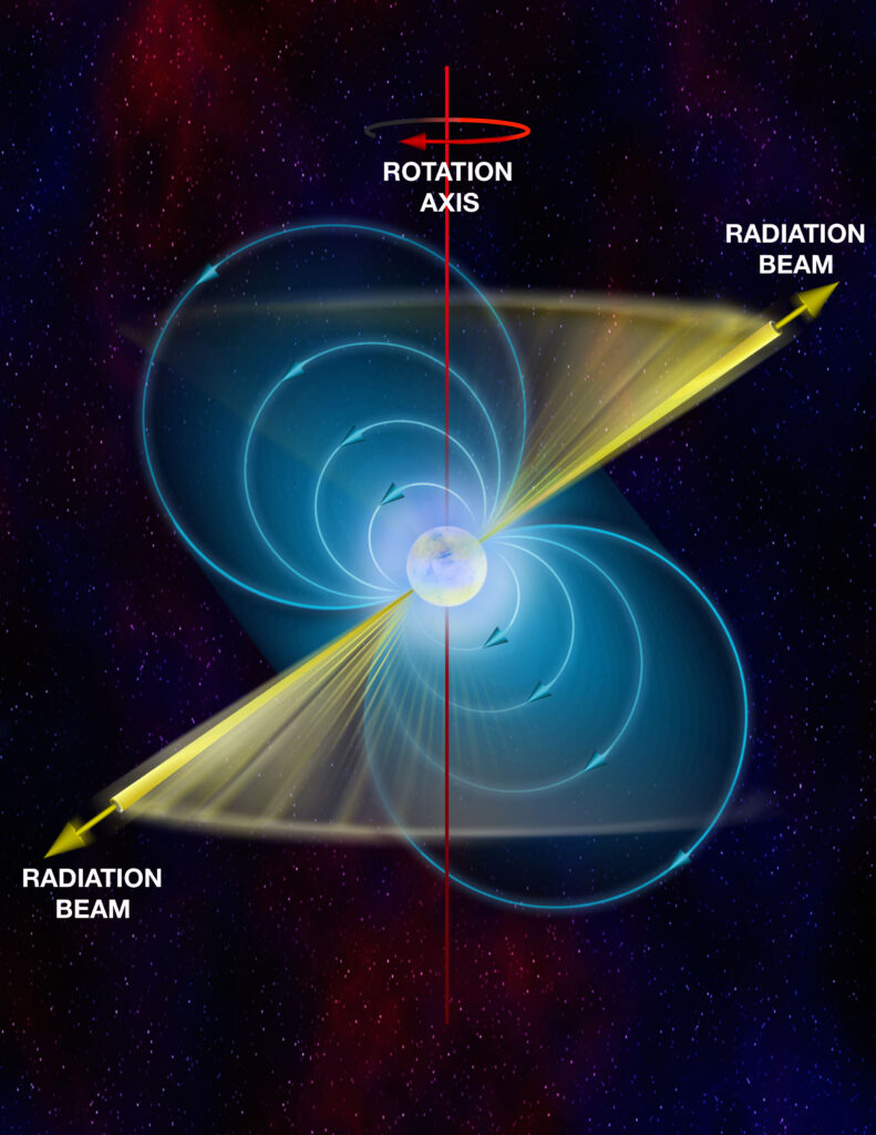
Artistic interpretation of a pulsar by B. Saxton, NRAO/AUI/NSF, featured in accordance with the NRAO’s media use policy and the Creative Commons Attribution 3.0 Unported license.
This article was composed in partner with Andreas Buzan, Alyssa Manus, and Ruby McGhee. Please see the credits for more information.
Data Collection
We used Skynet’s 20m-diameter radio telescope at Green Bank Observatory to detect the pulsars PSR 1919+21 and PSR 0950+08 and used the substitute data provided by Skynet user bddean21 for PSR 0329+54, since our initial observation was unsuccessful and did not load into the graph. We can do this even if pulses are below the noise level by measuring the pulsar’s rotation-period and then producing period folded pulse profiles. Then we tried to detect if the signal is polarized for the brightest pulsar, PSR 0329+54: this would rule out thermal emission which is never polarized, but non-thermal emission involving magnetic fields can be highly polarized. Lastly using the period measurements, we placed an upper limit on the size of pulsars or neutron stars.
We used the Green Bank Observatory’s 20 m’s L-band receiver, which detects radio waves with frequencies between 1300 MHZ and 1800MHz. This allows us to be low in spectral resolution mode while using the “HI” bandpass filter which narrows the detector’s response to range between 1355-1435 MHz and removes human-made interference frequencies. This observation was different from our previous modules because we were not trying to take a picture, rather track a singular point in the sky as the Earth rotates beneath the telescope so we can collect measurements for a high cadence stream of brightness. We set our duration to 180 seconds (3 minutes) and set our Integration Time to 0.021 seconds.
Analysis Method
Light Curve
When the observation was complete, the raw data initially only indicated the brightness—or flux density—of the target that the telescope detected roughly every few milliseconds. Graphing the flux density (which, it should be noted, is in arbitrary uncalibrated units) over time produces a light curve like the one below.

Periodogram
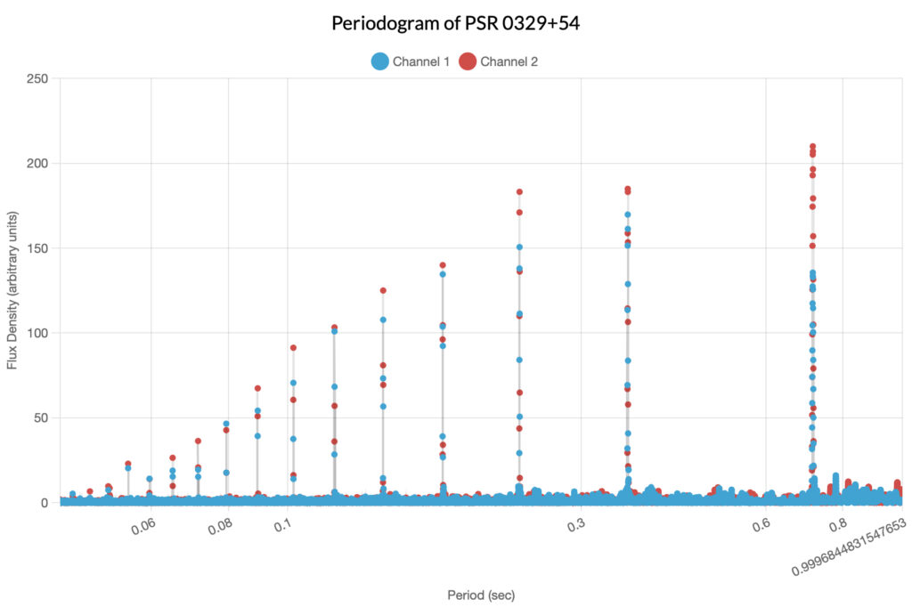
Suppose that we wanted to determine if the flux densities in the light curve have some kind of regularity or repeating period: for this we can use a periodogram. A periodogram interprets data in such a manner that it plots the intervals between similar flux density measurements to find a period of best fit. Consider the periodogram below and note how it reveals that the strongest measurements of flux density occur approximately every 0.71 seconds. We can actually inspect the periodogram more closely and determine a more precise value of 0.714551 seconds per period.
Period-Folded Light Curves
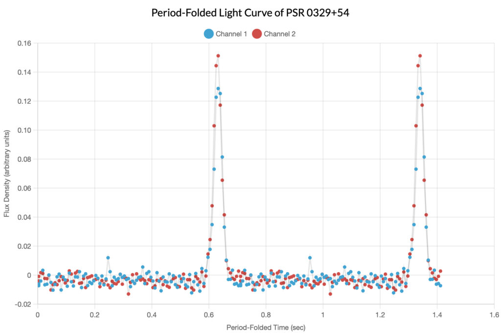
Okay, so now let’s suppose that we want to visualize what the initial light curve would look like if we superimposed every 0.714551 second period over itself so that we could see the highest measurements align: this is the function of the period folded-light curve. Below is the period-folded light curve of PSR 0329+54 where the y-axis is still flux density, and the x-axis is time. You may notice that the graph actually repeats after the 0.714551 second mark: this is done to better visualize the cyclical nature of the graph. One important thing to note is that this graph needs to be externally calibrated, and the process for that is discussed in the next section below.
Sonogram
One of the unique things about functions over time is their ability to be interpreted beyond static visual renderings. Audiovisual media is particularly useful for communicating the nature of data beyond simple tables or graphs. From the data contained in the graph above, a sonogram can be created where, over time, the data points are played as sounds that become louder as their flux densities increase. This creates a very good representation of the interval between the pulsar’s complete rotations as the graph is actually “read” out over time. Below is an audio file of the sonogram of the above period-folded light curve of PSR 0239+54; note that the frequency of the loud “clicks” is approximately 1.4Hz.
Calibration Method
Radio telescopes collect data in two orthogonal polarized channels. To determine that the signal of PSR 0329+54 was polarized, we calibrated the two channels with respect to each other using the unpolarized source Taurus A (TAU A), also known as the Crab Nebula, with data provided by Skynet user rjyete, since our initial observation was unsuccessful and did not load into the graph.
First, to calibrate one channel with respect to the other, we measured how bright TAU A was in both channels which helps us find much to multiply the second channel’s value by so it equals the first channel’s value (the calibration factor). We used a daisy pattern of moving the telescope in a small looping pattern over the source, so the signal rises and falls which mimics the behavior of a pulsar. We set the radius to 3 beams at 45 arcminutes per beam which equals 135 arcminutes with 4 petals for a duration of 60 seconds and an Integration Time of 0.3 seconds.
To figure out the calibration factor, we used the Skynet graphing tool to load in the data for TAU A onto a separate graph from our original PSR 0329+54. On the Light Curve page we set the background-subtraction timescale to 3, and on the Periodogram page, we set the period to range between 10 and 20 and found the actual period to be 0.529124 seconds. Then we fine-tuned this period in the Period Folding page by adjusting the Calibration factor to 0.8 making the two channels the same. Then, we returned to our first graph of PSR 0329+54 and entered this calibration factor and found the difference curve to stand out from the noise meaning that we detected a change in polarization as the hot spot of the neutron star swung by. Since we discovered that PSR 0329+54 was polarized: this means that the emission mechanism was non-thermal emission involving magnetic fields which can be highly polarized.
Implications of Polarization
When a star reaches the end of its life cycle and collapses, it leaves behind a small spherical, hyper-dense iron core, still rotating with the speed as the newly dead star. This means that these tiny objects are rotating with tremendous speeds. The rotation speed, when paired with its density and composition, give the pulsar a tremendously strong magnetic field. The fields are so strong that at the poles of the star are strong enough to spew out charged particles at tremendous rates that can be seen in radio waves. As the neutron star rotates, if its axis of rotation aligns with its poles, we won’t see any sign of its spin. If the axis and poles aren’t aligned and one of the beams from the poles happens to hit the Earth, we see this as a periodic pulsing of radiation (pulsars)! Because the magnetic field of the pulsar is curved, as the beam of radiation passes over the Earth, we can see the radiation at the start of the pulse concentrated in one direction, but at the end of the pulse oriented another direction. For example, if the radio waves are concentrated to the right at the start of the pulse, then maybe by the end of the pulse the waves are concentrated to the left!
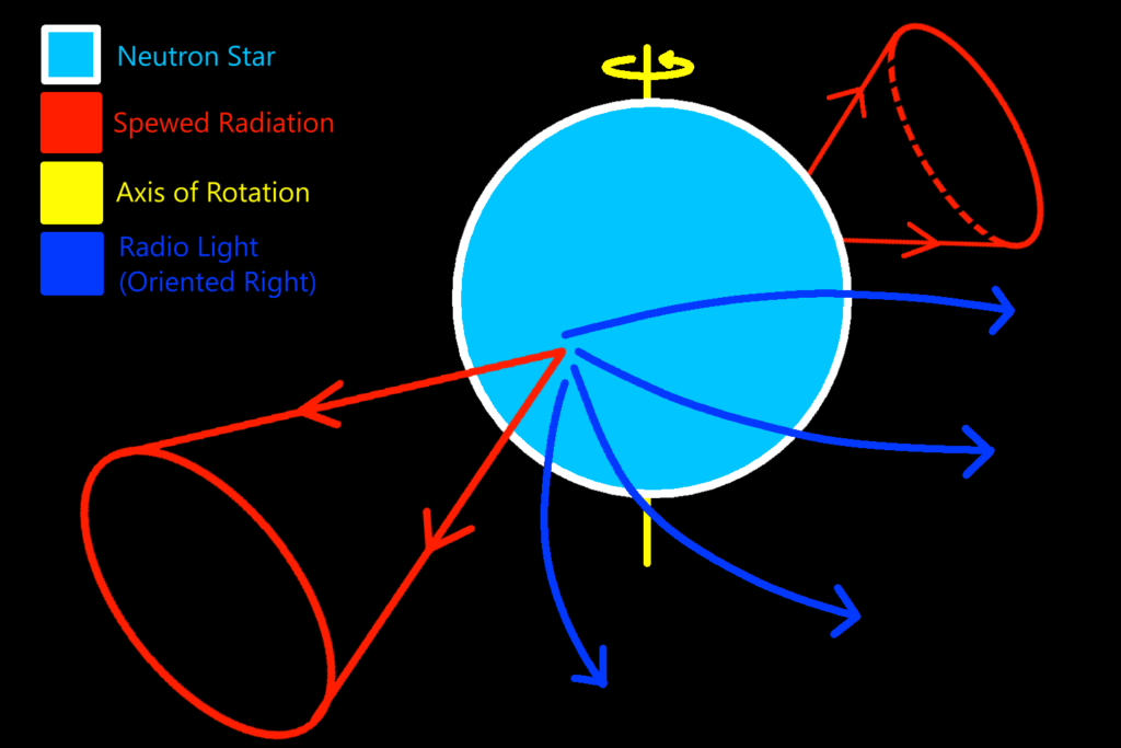
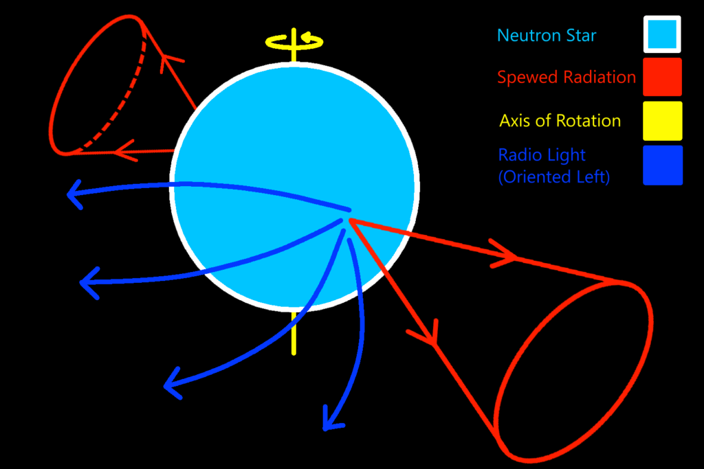
The blue lines in the above diagrams represent the radiation being skewed by the pulsar’s magnetic field, which originates and moves in all directions from the poles of the star. This skewed radiation is what is picked up as polarization. Of course, this is not always detectable. When the pole of the pulsar does not sweep directly over the Earth, the light will look all oriented the same way.
Continued Analysis
PSR 0950+08
Using Skynet Plotting, we use the Pulsar tool to upload our radio observation file from PSR 0950+08. Under the Periodogram tab, we first increase the Points from 1000 to 10000. This is because we want to get the most precise measurement, and more points will help achieve this. From here, we can tell that the period peak occurs somewhere near 0.25 seconds. Making sure that we are in Period mode, we use the Start Period and Stop Period controls to zoom in on the peak. This will allow us to see the exact peak point more easily. We can now tell the period to five or six decimal places. 0.25307 seconds seems to be where the highest point is.
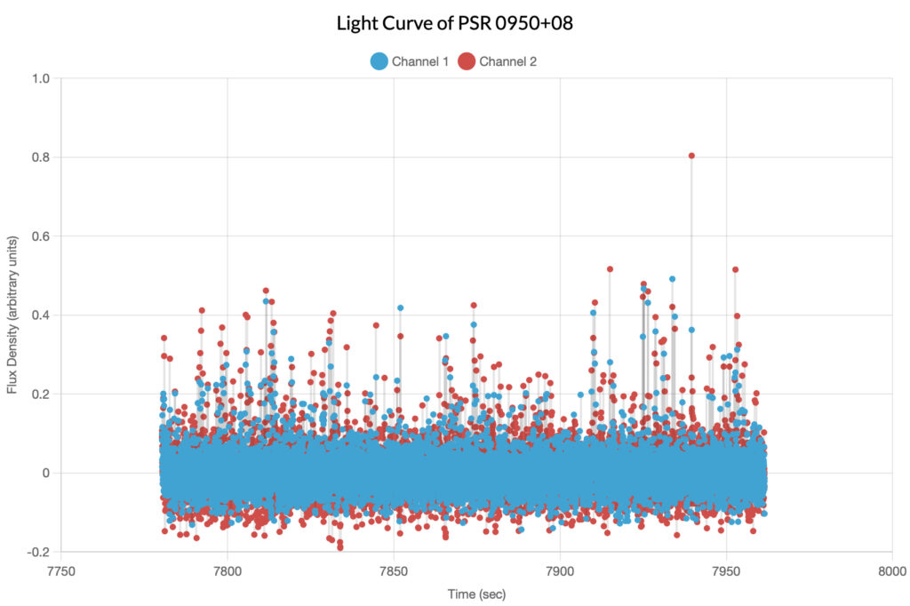

Now, under the Period Folding tab, we can change the Period to 0.25307 seconds, a more accurate number. This gives us a folded light curve.
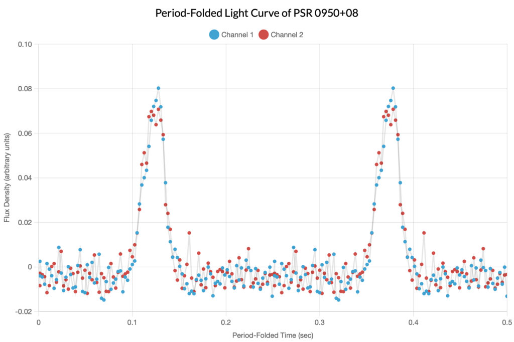
Compared to PSR 0329+54, PSR 0950+08 has a much shorter period. From this, we can conclude that PSR 0950+08 is smaller.
Bonus Content
Overview
For the sake of interest, the website’s author has included many of the graphs and sonograms not used in the original post, including his own radio observation in which you can see what happens in the graphing software when a pulsar is not detected. The author hopes that you will find at least passing interest in them with minimal commentary.
PSR 2021+51
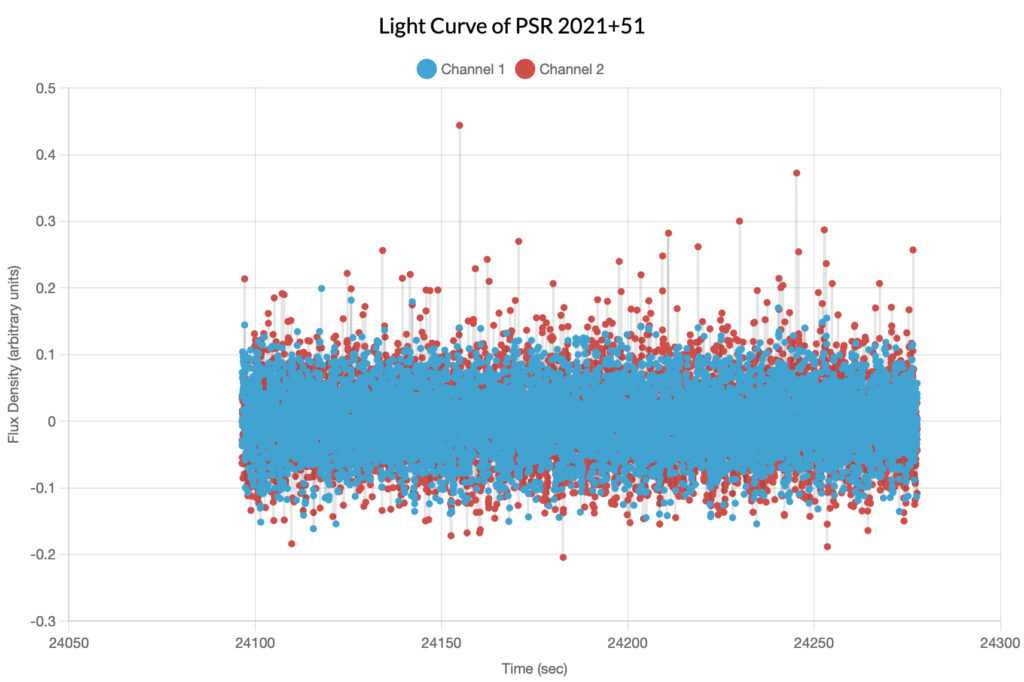
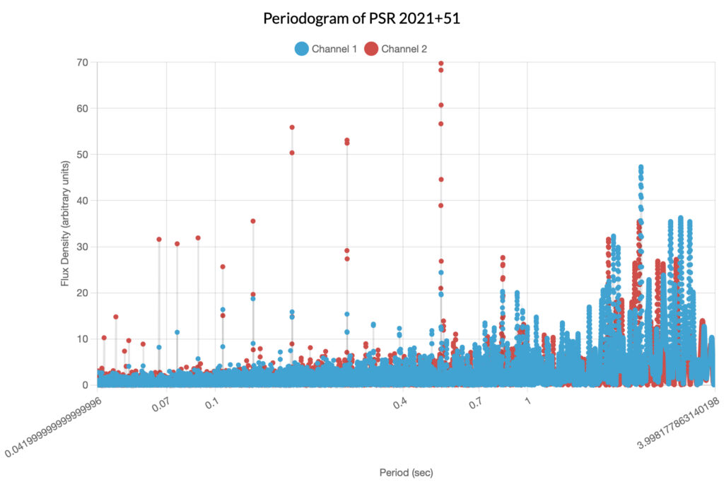
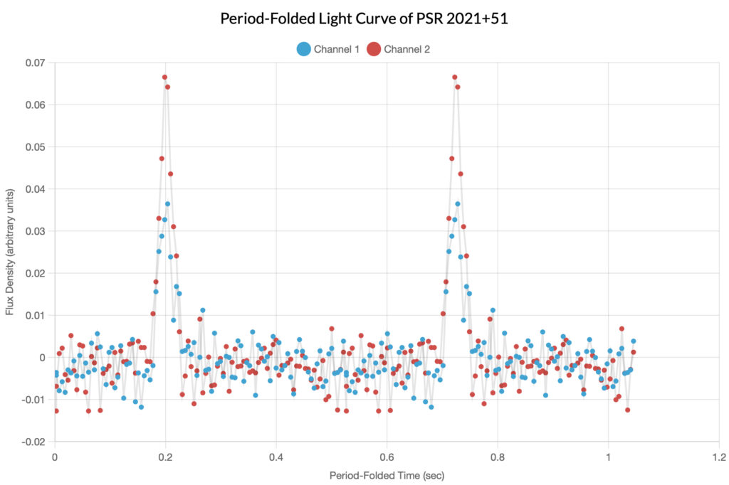
Described as of moderate difficulty to detect, this pulsar was observed by one of the authors of the original article. Unfortunately, her data would not load into the graphing tool and was substituted by data from Skynet user manusrinivas. The determined period of this pulsar was 0.529124 seconds; note that in the folded light curve, the signal is polarized.
PSR 0929+10
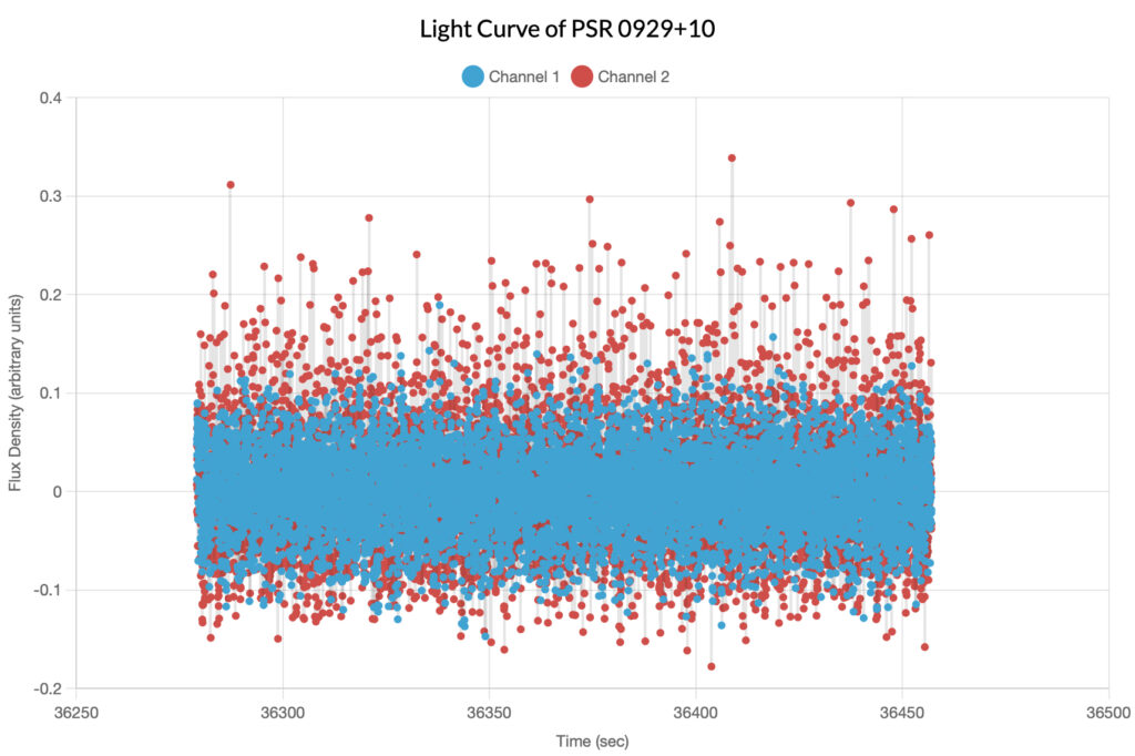
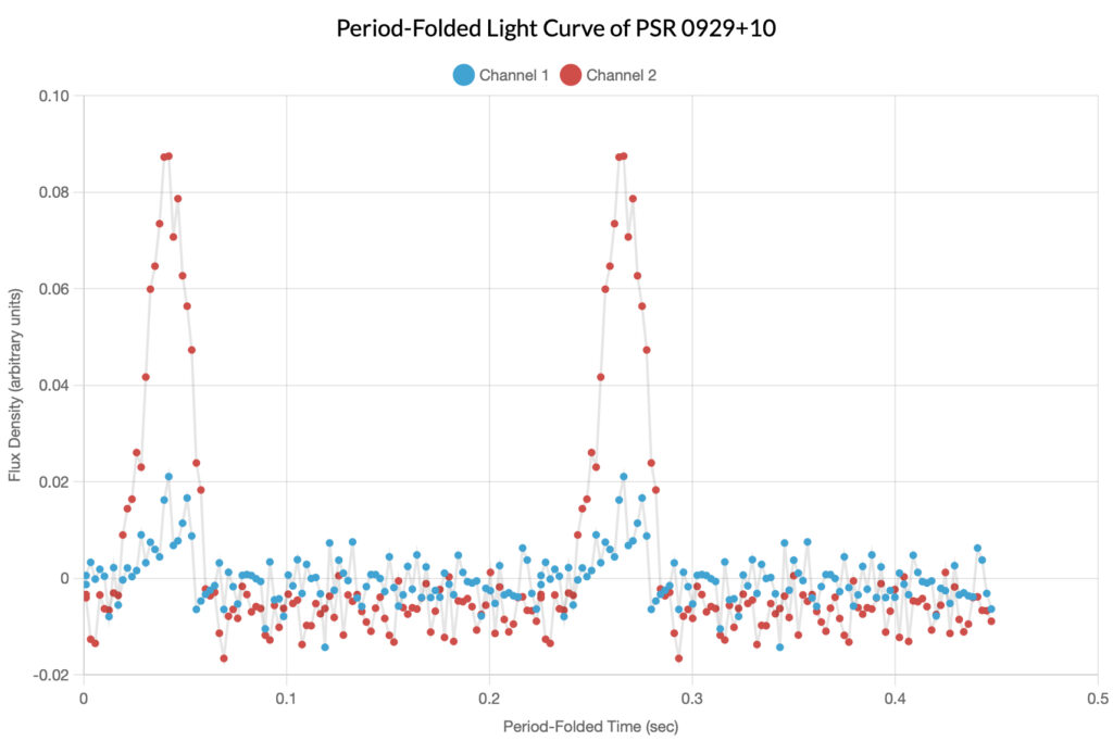
Described as the most difficult pulsar available to be observed, initially the authors of the original article declined to observe it; one of their colleagues, Skynet user vdvoyan, however, managed to observe it, and their data is featured here. The determined period of this pulsar was 0.226489 seconds; note that in the folded light curve, the signal is heavily polarized.

PSR 1919+21
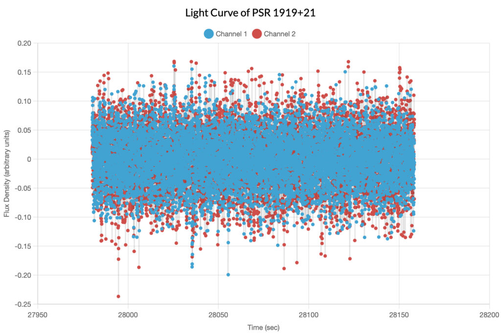
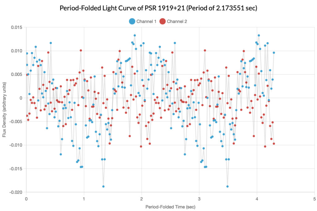
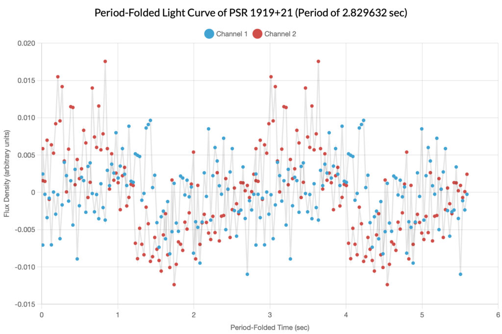
Described as moderately difficult, the website author’s own pulsar observation was able to be loaded into the graphing tool, but was unable to detect a pulsar. In these graphs, we can see what happens when trying to find periodicity in noise.

In the periodogram above, there are two major spikes in both channels; the author decided to make two folded light curves and sonograms based on each spike.
Taurus A
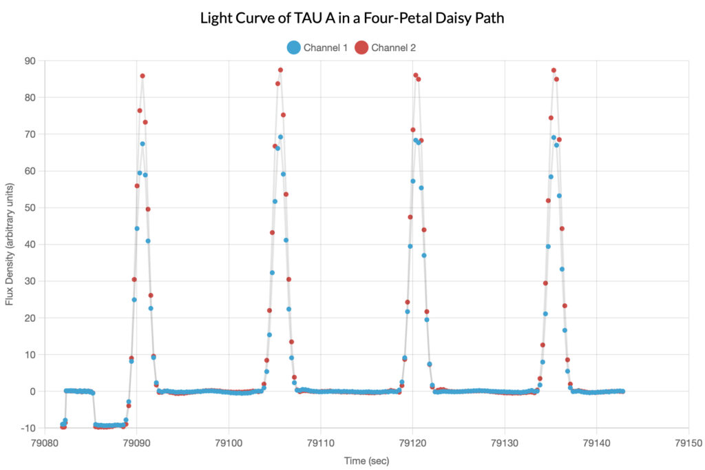
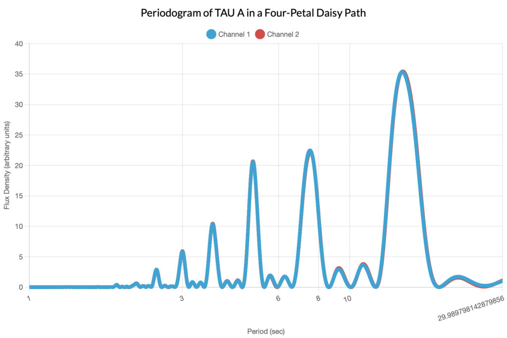
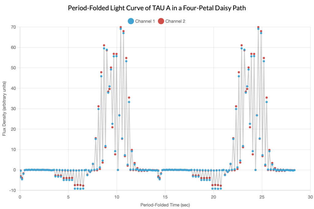
For the sake of completeness, the author has included the graphs of the calibration source TAU A (the Crab Nebula). Remember that the observing telescope used a four-petal daisy path to move the sensor across the source, so the periodicity of the light curve below is entirely artificial.
Bonus Sonograms
The data used to create the sonograms below was formatted and provided to the authors by their instructor. These are sonograms of three of the fastest pulsars, including the fastest pulsar PSR J1748−2446ad.
WARNING: THESE SONOGRAMS MAY BE EXCEEDINGLY LOUD, CAUTION IS ADVISED FOR READERS WEARING HEADPHONES OR USING LARGE SPEAKERS.
Credits
Thank you to Andreas Buzan for providing the data for PSR 0329+54, creating the pulsar diagrams featured in the Implications of Polarization section, and for writing that same section. Andreas maintains his own blog at tarheels.live/blogandreas/.
As well, thank you to Alyssa Manus for providing the data for PSR 0950+08 and writing the section describing it. She also runs her own blog at alyssacmanus.wixsite.com/astrophotography.
And as well, thank you to Ruby McGhee for writing the sections on how the data was measured and calibrated. Her blog can be found at tarheels.live/rubymcghee/.
Also, thank you to Dan Reichart for providing the data for the sonograms of some of the fastest pulsars. His blog can be found at www.danreichart.com/afterglow-astrophotography.
And finally, thank you to Skynet users bddean21, rjyete, and manusrinivas for the use of their data.
Proudly powered by WordPress
